Erzeugt einen tiefen, lauten Klang ähnlich den Nebelsignalhörnern des Schiffes.
 Sichere Zahlungen
Sie können sicher mit Karte, PayPal, Amazon Pay oder Banküberweisung bezahlen
 Lieferbedingungen
Express-Sendungen mit DHL, BRT, GLS
 Rücknahmegarantie
Sie haben 15 Tage ab Lieferung Zeit, um das Produkt zurückzusenden, wenn Sie nicht zufrieden sind
Attenzione, il prodotto è un KIT e pertanto vi verranno consegnati i componenti da saldare con un saldatore per elettronica e tutto l'occorrente per ricreare l'apparato come da immagine. Nel KIT sono comprese istruzioni illustrate in lingua inglese di facile comprensione.
LIVELLO ESPERIENZA NECESSARIO basso
Disponibile anche il montaggio e collaudo da parte di Mectronica STORE aggiungendo quantità 10 del Servizio montaggio KIT acquistabile cliccando qui su EBAY | MECTRONICA STORE ed aggiungendolo al carrello insieme al KIT da montare.
DISPONIBILE ANCHE IL CONTENITORE CASE al codice G027N che puoi cercare direttamente nel nostro store!
Genera un suono profondo e rumoroso simile alle corna del segnale di nebbia delle navi.
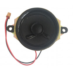
È necessario collegare un altoparlante da 8 ohm (NON INCLUSO) per azionare il tromboncino. Parecchi gli altoparlanti dovrebbero essere testati ascoltando per scegliere l'altoparlante con la massima fedeltà e il più alto livello di volume. È necessario utilizzare un altoparlante incorporato in modo che il telaio funziona come una scheda audio. Ne risulta un altoparlante con un telaio aperto un suono scarso e troppo basso. La clip di raffreddamento collegata deve essere fissata sul transistor T2. Il transistor deve essere spinto sul suo bordo nella clip di raffreddamento e deve adattarsi strettamente dentro. La clip di raffreddamento potrebbe non entrare in contatto con nessun'altra parte metallica ma il transistor; lo farà anche ricevere un rifornimento d'aria sufficiente.
Il suono richiesto deve essere regolato con il trimmer "P1". Per favore presta attenzione a sufficiente energia elettrica! L'unità richiede un'alimentazione di 300 mA, a seconda sulla tensione! Se la sirena della nebbia non funziona correttamente durante il funzionamento della batteria (babyor monocelle), la resistenza interna delle batterie potrebbe essere troppo alta. In questo caso, un condensatore elettrolitico da 1000 μF a 16 V (tra + e -) deve essere montato parallelamente a la connessione di tensione della scheda.
Sostituzione del resistore R1: il trimmer è reattivo per le regolazioni di frequenza. Per più regolazioni di frequenza il resistore R1 può essere sostituito da 220 KΩ a 820 Varianti KΩ.
SPECIFICHE:
It is required to connect a loudspeaker of 8 ohms to operate the fog-horn. Several loudspeakers should be tested by listening to chose that loudspeaker with best fidelity and highest volume level. It is required to use a built-in loudspeaker so that the chassis functions as a sound-board. A loudspeaker with an open chassis results in a poor and too low sound. The attached cooling clip has to be fixed on the transistor T2. The transistor is to be pushed to its edge into the cooling clip and must fit tight in it. The cooling clip may not contact any other metal part but the transistor; it shall also receive sufficient air supply.
The requested sound is to be adjusted with the trimmer “P1”. Please pay attention to sufficient power supply! The unit requires a power supply of 300 mA, depending on the voltage! If the fog horn doesn‘t work properly during battery operation (babyor monocells), the internal resistance of the batteries may be too high. In this case, an electrolytic capacitor 1000 µF 16 V (between + and -) should be fitted parallel to the voltage connection of the board.
Replacing resistor R1: The trimmer is responsive for frequency adjustments. For more frequency adjustments the resistor R1 can be replaces with 220 KΩ to 820 KΩ variants.
Technical data:
Kit: to solder yourself | Operating voltage: 4,5 - 12 V/DC | Frequency of tone:
adjustable | Loudspeaker connection: 8 Ohm | Power: max. 5 W depending on the
voltage | Dimensions of the board: approx. 44 x 20 mm

Erzeugt einen tiefen, lauten Klang ähnlich den Nebelsignalhörnern des Schiffes.