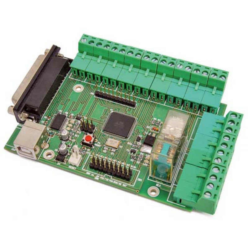


It allows to use, through the USB port of the PC, the traditional three-axis control cards of a CNC that work on parallel port.
 Secure payments
You can pay safely by Card, PayPal, Amazon Pay or Bank Transfer
 Delivery policy
Express shipments with DHL, BRT, GLS
 Return policy
You have 15 days from delivery to return the product if you are not satisfied
Based on the ATmega2560 with GRBL firmware installed, this board has a USB / TTL converter, DB25 connector, USB port for powering and connecting to the PC, relay output for connecting an electrospindle. It allows to use, through the USB port of the PC, the traditional three-axis control cards of a CNC that work on parallel port. Attention: The USB cable and the cable for connection to the RESET connector are not included in the package, therefore if necessary they must be purchased separately (see the related ones for the product codes). Buy all the accessories in our shop on EBAY | MECTRONICA STORE |
The system |
To understand the usefulness of the interface it must be said that in common CNCs on LPT port the command is given by the machining software (for example Mach 3) which, starting from the file in G-code language, sends impulses directly to the parallel lines to advance the respective axes by a certain number of steps / mm. Mach 3 executes the G-code and emits specific pulses for the motors, one per pin of the parallel, synchronized and time coherent. If you tried to communicate via USB with a converter, first of all a virtual LPT corresponding to the USB would be opened with the appropriate drivers, then the data would be serialized and then transferred along the USB to the USB / parallel converter, The parallel reconstruction of the command impulses starting from the commands received on USB is carried out by an ATmega2560 microcontroller interfaced to a USB / TTL converter; in the microcontroller we loaded the grbl firmware. Then our board receives the G-Code coordinates from USB and locally generates the impulses on its parallel, which drives the original printer controller. |
The firmware |
The firmware installed is grbl, not compatible with Mach3, so we must orient ourselves, for the CNC control software, towards suitable solutions. Grbl is a firmware created to interpret the G-code language and convert it into commands on the three axes of a CNC machine; then the G-code sends the displacement coordinates on the three axes (for example, to draw a square you need 4 coordinates and therefore 4 commands: from one point to a second, from the second to the third, from the third to the fourth and from this to the first) . The machine converts the coordinates into steps to be given to the motor (taking into account the microsteps) to make the movements required by the commands. Grbl was designed for the MEGA world and can therefore be installed on cards based on ATmega microcontrollers from Atmel with the bootloader preloaded using the same IDE MEGA. In our case, being an open firmware, we have customized it by modifying some parts, especially those that define the structure of the CNC to which the controller board will be combined. The firmware can be downloaded from github. The conversion of G-code instructions into direct commands to the axis drive motors follows certain rules and takes place according to a certain logic; grbl also supports some operating modes and standard management, such as those of the limit switches, the emergency stop button, the adjustment speed of the electric tool, etc. |