Questo originale kit permette di realizzare un mini bobina di Tesla che, generando l’alta tensione crea un piccolo fulmine che permette ad esempio di innescare una lampada al neon semplicemente avvicinandola alla bobina.
 Pagamenti Sicuri
Paga in totale sicurezza con Carta di Credito, PayPal, Amazon Pay, Bonifico Bancario o PostePay
 Spedizione Rapida
A partire da 6,49€ in 2–4 giorni o Express 24/48h a 9,90€ SDA, UPS, DHL, BRT, Punto Poste o Ritiro
 Reso Facile 30 Giorni
Hai 30 giorni dalla consegna per restituire il prodotto se non sei soddisfatto
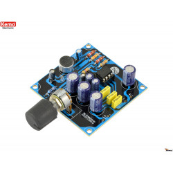
Attenzione, il prodotto è un KIT e pertanto vi verranno consegnati i componenti da saldare con un normale saldatore per elettronica e tutto l'occorrente per ricreare l'apparato come da immagine.
LIVELLO ESPERIENZA NECESSARIO medio-alto
Disponibile anche il montaggio e collaudo da parte di Mectronica STORE aggiungendo quantità PEZZI 20 del Servizio montaggio KIT acquistabile cliccando qui su EBAY | MECTRONICA STORE ed aggiungendolo al carrello insieme al KIT da montare.
Questo originale kit permette di realizzare un mini bobina di Tesla che, generando l’alta tensione crea un piccolo fulmine che permette ad esempio di innescare una lampada al neon semplicemente avvicinandola alla bobina. Il kit prevede anche un ingresso audio che modula il generatore accendendo e spegnendo l'arco a ritmo di musica: l’audio, applicato al suo ingresso, stimola il plasma ad arco trasformandolo in vibrazioni d'aria, riproducendo così il suono. Alimentazione: da 15 a 24 VDC – 2 A (24 VDC consigliata).
Specifiche tecniche
Componenti:
- R1, R4: 10 kohm
- R3, R5: 2 kohm
- C1: 1 µF elettrolitico
- C2: 1 µF multistrato
- Q1: IRF530
- Q2: TIP141
- LED1, LED2: LED rosso 3 mm
- L1: spezzone di filo avvolto intorno a L2
- L2: bobina di TESLA
- J1: plug DC da c.s.
- J2: presa Jack audio 3,5 mm
Assemblaggio
Iniziate il montaggio dei componenti partendo dalle resistenze (R1, R3, R4, R5) e proseguendo con la presa jack audio (J2), il condensatore elettrolitico C1 e C2, i LED (LED1 e LED2), il plug d’alimentazione (J1) e il connettore d’alimentazione J3 (se preferite alimentare il circuito da quello); montate poi in piedi e ciascuno con il lato metallico rivolto all’esterno del PCB, il MOSFET IRF530 (Q1) e il transistor NPN TIP41 (Q2), cui applicherete poi il dissipatore in allumino da 13°C/W.
Il secondario HT (alta tensione) è formato da 350 spire di filo in rame smaltato da 0,2 mm di diametro avvolte (bloccate con del nastro adesivo per non farle muovere) su supporto cilindrico in plastica di 20 mm lungo circa 60 mm.
Raschiate delicatamente con la lama di un coltello o di una forbice lo smalto dalle estremità (avete rimosso lo smalto quando il filo cambia di colore, divenendo più rosa che giallastro) in modo da togliere l’isolante e facilitare la saldatura del capo che va sul PCB (piazzola L2). L’altro capo della bobina, ovvero quello verso l’alto, rimarrà libero. Consigliamo di fissare la base della bobina di TESLA al PCB con della colla tipo Attak.
Per il primario dovete avvolgere una o due spire con il filo elettrico unipolare rigido da 0,5 mm di diametro (filo rosso contenuto nel kit), direttamente sopra il secondario HT. I capi del primario vanno poi saldati nelle rispettive piazzole del PCB, che sono siglate L1.
Il circuito stampato, per l’utilizzo, andrà posto su una base in materiale isolante, quindi legno secco o plastica, in modo che nessuna delle sue piazzole tocchi parti o piani in metallo. Potete anche pensare a un contenitore in plastica da cui far fuoriuscire la parte alta del trasformatore e il capo libero del secondario, in modo da favorire la scarica o da poterlo connettere a un corpo da cui vorrete far partire l’effluvio.
Collaudo
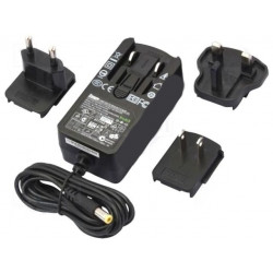
Procuriamoci un alimentatore da rete che fornisca all’uscita una tensione continua di 15 V, che possa erogare una corrente di 2 ampere e che disponga di un cavetto terminante con un jack coassiale avente diametro adatto alla presa jack DC del circuito. La polarità del connettore su scheda è positiva sul polo centrale e negativa su quello esterno, quindi il jack dell’alimentatore dovrà essere tale.
Il filo di estremità del secondario rimasto libero va portato in fuori in modo che alimentando il circuito produca un alone luminoso dovuto alla scarica a corona che causa la ionizzazione dell’aria e può arrivare alla conseguente produzione d’ozono; dal filo si rilascia l’effluvio elettrostatico, visibile come un alone a cono con luce molto intensa in prossimità del filo e sfumata man mano che ci si allontana. All’emissione della scarica sarà associato un rumore caratteristico simile a un soffio ritmico; i due fenomeni saranno maggiormente accentuati se la massa del circuito verrà collegata a un’estesa lamina metallica posta sul piano d’appoggio del generatore, fermo restando che essa dovrà rimanere distante almeno una decina di centimetri dall’elettrodo libero del secondario del trasformatore.
Avvicinando una lampadina al neon o una a risparmio energetico (purché basata su tubo al neon) la vedremo illuminare, sia pure più debolmente di come si illuminerebbe se venisse alimentata normalmente: tale fenomeno è dovuto alla ionizzazione del gas contenuto nella lampadina, ad opera del campo elettrico generato dal trasformatore.
Applicando all’ingresso audio il segnale di una fonte BF possiamo modulare l’effluvio elettrostatico e ottenere dalla sfera o da una placca metallica il suono corrispondente: prendiamo dunque un cavetto audio stereo avente alle estremità due jack da 3,5 mm e inseriamo un capo nella presa di uscita audio di un lettore MP3 o di uno smartphone, tablet o PC nel quale siano memorizzati brani audio, poi l’altro jack inseriamolo nella presa del circuito, che manterremo spento fino a quando avremo fatto i collegamenti. Avviamo la riproduzione e accendiamo il generatore d’alta tensione: variando il volume potremo sentire il debole suono generato dalla modulazione dell’effluvio elettrostatico (ossia del vento elettrico) ad opera del segnale ad audiofrequenza.
Misure di sicurezza
ATTENZIONE !
Il circuito funziona ad alta tensione e richiede quindi le cautele del caso: quando è in funzione e nei primi minuti dopo lo spegnimento, non toccate lo stampato né altri componenti, ad evitare di prendere una scossa che per i più è solo dolorosa ma che per un cardiopatico può essere pericolosa.
Non mettere telefoni cellulari, lettori MP3 e altre apparecchiature elettroniche vicino alla bobina, perché quest’ultima genera un campo elettromagnetico ad alta frequenza che potrebbe provocare interferenze e danneggiarli.
Per quanto la corrente che il trasformatore può rilasciare sia bassissima (intorno al milliampere) la tensione sviluppata è molto elevata e potrebbe dare una scossa dolorosa; avvicinarsi all’estremità libera del secondario e a qualsiasi corpo collegato ad essa può far partire verso di sè e questo fenomeno potrebbe dare una sensazione di bruciore.
Dopo un utilizzo prolungato, non dovete toccare il dissipatore di calore del transistor TIP41 e del MOSFET, perché la temperatura che possono assumere è molto elevata, soprattutto se il circuito l
Attention, the product is a KIT and therefore you will be given the components to be welded with a normal soldering iron for electronics and everything you need to recreate the apparatus as shown in the image.
EXPERIENCE LEVEL REQUIRED medium-high
Assembly and testing by Mectronica STORE is also available by adding 20 PIECES of the KIT assembly service which can be purchased by clicking here on EBAY | MECTRONICA STORE and adding it to the cart together with the KIT to be assembled.
This original kit allows you to create a Tesla mini coil which, by generating high voltage, creates a small lightning bolt that allows for example to trigger a neon lamp simply by bringing it closer to the coil. The kit also includes an audio input that modulates the generator by turning the arc on and off to the rhythm of music: the audio, applied to its input, stimulates the arc plasma transforming it into air vibrations, thus reproducing the sound. Power supply: from 15 to 24 VDC - 2 A (24 VDC recommended).
Technical specifications
• Power supply: from 15 to 24 VDC
• Maximum absorbed current: 2 A
• High voltage generated: 2.1 kV at 13 Vdc
• Audio input: 3.5 mm jack (you can connect the phone, an MP3 player, the audio output of the computer, etc.)
• Assembled dimensions (mm): 76x80x40
Components:
- R1, R4: 10 kohm
- R3, R5: 2 kohm
- C1: 1 µF electrolytic
- C2: 1 µF multilayer
- Q1: IRF530
- Q2: TIP141
- LED1, LED2: red LED 3 mm
- L1: piece of wire wrapped around L2
- L2: coil of TESLA
- J1: DC plug from c.s.
- J2: 3.5mm audio jack socket
assembling
Start the assembly of the components starting from the resistors (R1, R3, R4, R5) and continuing with the audio jack socket (J2), the electrolytic capacitor C1 and C2, the LEDs (LED1 and LED2), the power plug (J1 ) and the power connector J3 (if you prefer to power the circuit from that); then mounted standing and each with the metal side facing the outside of the PCB, the MOSFET IRF530 (Q1) and the NPN TIP41 transistor (Q2), to which you will then apply the 13 ° C / W aluminum heat sink.
The secondary HT (high voltage) is made up of 350 turns of enameled copper wire of 0.2 mm in diameter wound (blocked with adhesive tape to keep them from moving) on a 20 mm cylindrical plastic support about 60 mm long.
Gently scrape the enamel from the ends with the blade of a knife or scissors (you have removed the enamel when the thread changes color, becoming more pink than yellowish) in order to remove the insulation and facilitate the welding of the garment that goes on the PCB (stand L2). The other end of the coil, i.e. the one facing upwards, will remain free. We recommend fixing the base of the TESLA coil to the PCB with Attak glue.
For the primary winding, you have to wind one or two turns with the 0.5 mm diameter single-pole rigid electric wire (red wire contained in the kit), directly above the secondary HT. The heads of the primary must then be welded in the respective pads of the PCB, which are initialed L1.
The printed circuit, for use, will be placed on an insulating material base, then dry wood or plastic, so that none of its pads touch metal parts or surfaces. You can also think of a plastic container from which to make the upper part of the transformer and the free end of the secondary flow out, so as to facilitate the discharge or to be able to connect it to a body from which you want to leave the effluvium.
Testing
Let's get a power supply that supplies a 15 V DC voltage at the output, which can supply a current of 2 amps and which has a cable ending with a coaxial jack having a diameter suitable for the DC jack socket of the circuit. The polarity of the connector on the board is positive on the central pole and negative on the external one, therefore the power supply jack must be such.
The end wire of the secondary that has remained free must be brought out so that by feeding the circuit it produces a luminous halo due to the corona discharge which causes the ionization of the air and can lead to the consequent ozone production; the electrostatic effluvium is released from the wire, visible as a cone halo with very intense light near the wire and faded away as you move away. The emission of the shock will be associated with a characteristic noise similar to a rhythmic murmur; the two phenomena will be more accentuated if the circuit mass is connected to an extended metal sheet placed on the generator support surface, it being understood that it must remain at least ten centimeters away from the free electrode of the transformer secondary.
Approaching a neon bulb or an energy-saving one (provided it is based on a neon tube) we will see it illuminate, albeit more dimly than it would illuminate if it were powered normally: this phenomenon is due to the ionization of the gas contained in the bulb, by the electric field generated by the transformer.
By applying the signal of a BF source to the audio input we can modulate the electrostatic effluvium and obtain the corresponding sound from the sphere or from a metal plate: therefore we take a stereo audio cable with two 3.5 mm jacks at the ends and insert a head in the audio output socket of an MP3 player or a smartphone, tablet or PC in which audio tracks are stored, then the other jack insert it into the circuit socket, which we will keep off until we have made the connections. We start playback and turn on the high voltage generator: by varying the volume we will be able to hear the weak sound generated by the modulation of the electrostatic effluvium (i.e. the electric wind) by the audio frequency signal.
Security measures
WARNING !
The circuit operates at high voltage and therefore requires the necessary precautions: when it is in operation and in the first minutes after switching off, do not touch the printout or other components, to avoid taking a shock which for the most part is only painful but which for a heart patient can be dangerous.
Do not place cell phones, MP3 players and other electronic equipment near the coil, because the coil generates a high frequency electromagnetic field that could cause interference and damage them.
Although the current that the transformer can release is very low (around the milliampere) the voltage developed is very high and could give a painful shock; approaching the free end of the secondary and any body connected to it can start towards you and this phenomenon could give a burning sensation.
After prolonged use, you must not touch the heat sink of the TIP41 transistor and the MOSFET, because the temperature they can assume is very high, especially if the circuit is powered by 24V.

Potrebbe anche piacerti
Questo originale kit permette di realizzare un mini bobina di Tesla che, generando l’alta tensione crea un piccolo fulmine che permette ad esempio di innescare una lampada al neon semplicemente avvicinandola alla bobina.