Aurel RX-4MHCS-4B-Modul von Aurel, einem Überlagerungshybrid mit einem 433,92-MHz-Empfänger und HCS-Decodierung.
 Sichere Zahlungen
Bezahlen Sie sicher mit Kreditkarte, PayPal, Amazon Pay oder Banküberweisung
 Schneller Versand
Wir liefern in ganz Europa und weltweit mit UPS, DHL und DPD
 Einfache Rückgabe in 30 Tagen
Sie haben 30 Tage ab Lieferung Zeit, das Produkt zurückzugeben, wenn Sie nicht zufrieden sind
IL PRODOTTO VIENE FORNITO MONTATO E COLLAUDATO
Disponibile anche in KIT codice FT1179K o in SET con telecomando codice M1179MKIT
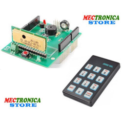
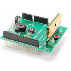
Basato sul modulo RX-4MHCS-4B dell'Aurel, un ibrido supereterodina contenente un ricevitore a 433,92 MHz completo di decodifica HCS, l’RF Shield consente di realizzare un ricevitore a 8 canali basato su Arduino, estendibile a 12 e controllabile tramite apposito radiocomando siglato TX-12CH. Lo sketch caricato su Arduino permette di leggere, elaborare i dati in arrivo e usarli per generare i comandi I²C-Bus con i quali gestisce lo shield a relé 7100-FT1079K (non compreso). Lo shield dispone di un buzzer, un trimmer (alimentato dagli stessi 5 volt che alimentano l'ibrido), di cui Arduino legge il cursore tramite la linea analogica A2 (allo scopo di impostare il tempo di ritardo in rilascio nella modalità monostabile ritardata) e un LED (LD1) che viene acceso dalla linea D2 di Arduino quando viene ricevuto un codice riconosciuto valido, un dip switch a 2 poli con il quale si impostano le modalità di funzionamento del ricevitore (bistabile o astabile). Il modulo RX-4MHCS-4B viene alimentato tramite il 5V di Arduino ed è contornato dal pulsante P1 e dal LED LD2; i contatti d'antenna finiscono su una morsettiera miniatura che permette di connettere l'antenna ricevente, sia essa uno stilo lungo 17 cm (in questo caso si collega al solo morsetto ANT) o un'antenna esterna (nel qual caso alla morsettiera si collega il cavo schermato, con lo schermo a GND e il polo caldo ad ANT).
N.B. La scheda Arduino Uno e lo Shield Arduino I/O expander non sono compresi.
|
Librerie Arduino |
|
|
|
Per gestire lo shield I/O Expander è prevista una libreria Arduino che fornisce tutte le routine necessarie alla rilevazione degli shield collegati e alla relativa gestione degli I/O (potete scaricare tale libreria dal nostro sito www.elettronicain.it). La comunicazione con l’MCP23017 è basata sull’I²C-Bus, pertanto la libreria utilizza “Wire.h” di Arduino; è presente una funzione “begin(int i2cAddress)” per inizializzare il singolo shield identificato tramite indirizzo I²C, ed anche una “init()” per programmare correttamente i registri interni del chip secondo le nostre necessità, ed infine una “pinMode(int pin, int mode)” per indicare se i singoli pin di I/O sono input o output. |
|
|
|
Documentazione e link utili |
|
|
THE PRODUCT IS SUPPLIED ASSEMBLED AND TESTED
Also available in KIT code FT1179K or in SET with remote control code M1179MKIT
Based on the Aurel RX-4MHCS-4B module, a superheterodyne hybrid containing a 433.92 MHz receiver complete with HCS decoding, the RF Shield allows the creation of an 8-channel Arduino-based receiver, extendable to 12 and controllable via special remote control marked TX-12CH. The sketch loaded on Arduino allows to read, process the incoming data and use them to generate the I²C-Bus commands with which it manages the relay shield 7100-FT1079K (not included). The shield has a buzzer, a trimmer (powered by the same 5 volts that power the hybrid), of which Arduino reads the cursor through the analog line A2 (in order to set the delay time in release in the monostable delayed mode) and an LED (LD1) which is switched on by the Arduino D2 line when a recognized valid code is received, a 2-pole dip switch with which the operating modes of the receiver are set (bistable or astable). The RX-4MHCS-4B module is powered by the Arduino 5V and is surrounded by the P1 button and the LD2 LED; the antenna contacts end up on a miniature terminal board that allows you to connect the receiving antenna, be it a 17 cm long stylus (in this case it connects only to the ANT terminal) or an external antenna (in which case you connect to the terminal block the shielded cable, with the GND shield and the hot pole to ANT).
N.B. The Arduino Uno card and the Shield Arduino I / O expander are not included.
Arduino libraries
To manage the I / O Expander shield there is an Arduino library that provides all the necessary routines for the detection of the connected shields and the relative I / O management (you can download this library from our website www.elettronicain.it). Communication with the MCP23017 is based on the I²C-Bus, therefore the library uses Arduino's "Wire.h"; there is a function "begin (int i2cAddress)" to initialize the single shield identified by the I²C address, and also an "init ()" to correctly program the internal registers of the chip according to our needs, and finally a "pinMode (int pin , int mode) ”to indicate if the individual I / O pins are input or output.
In addition to the initialization functions, the instructions we are particularly interested in are the "digitalRead (int pin)", "digitalWrite (int pin, int val)", "digitalWordRead ()" and "digitalWordWrite (word w)" which, respectively , allow you to read the status of a single input pin, write a single output pin, read the status of all the input pins (8 in our case) and finally write the status of all the output pins (always 8) . Input management can be done via interrupt; therefore, there is a special "pinDisableINT (int pin)" function that allows you to configure the single pin as an interrupter generator or not (in particular applications it might be useful to have the possibility of not setting all the input pins as interrupt generators, but do it selectively). As for the HCS shield, it does not require libraries but is managed directly by the sketch.

Technische Daten
Vielleicht gefällt Ihnen auch
Aurel RX-4MHCS-4B-Modul von Aurel, einem Überlagerungshybrid mit einem 433,92-MHz-Empfänger und HCS-Decodierung.