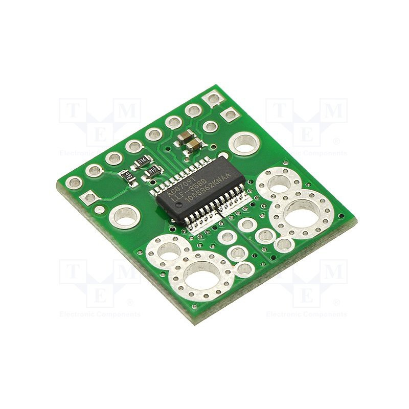


Hall-Effekt-Gleichstromsensor -35-35A integrierter ACS709-Spannungsausgang 0-5 V Arduino kompatibles Netzteil 3-5,5 V Gleichstrom.
 Sichere Zahlungen
Bezahlen Sie sicher mit Kreditkarte, PayPal, Amazon Pay oder Banküberweisung
 Schneller Versand
Wir liefern in ganz Europa und weltweit mit UPS, DHL und DPD
 Einfache Rückgabe in 30 Tagen
Sie haben 30 Tage ab Lieferung Zeit, das Produkt zurückzugeben, wenn Sie nicht zufrieden sind
Sensore corrente DC ad effetto hall -35-35A integrato ACS709 uscita in tensione 0-5V Arduino compatibile alimentazione 3-5,5V DC.
This current sensor is a carrier board or breakout board for Allegro’s ACS709LLFTR-35BB-T Hall effect-based linear current sensor with overcurrent fault output; we therefore recommend careful reading of the ACS709 datasheet (483k pdf) before using this product. The sensor has an operating voltage of 3 V to 5.5 V and an output sensitivity of 18.5 mV/A when Vcc is 3.3 V (or 28 mV/A when Vcc is 5 V).
The following list details some of the sensor’s key features:
Optimized accuracy for bidirectional input current from -37.5 A to 37.5 A, with a linear sensing range from -75 A to 75 A (see warning note below for thermal limitations).
Conductive path internal resistance is typically 1.1 mΩ, and the PCB is made with 2- oz copper, so very little power is lost in the board.
Integrated shield greatly reduces capacitive coupling from current conductor to die and prevents offset drift in high-side applications.
Use of a Hall effect sensor means the IC is able to electrically isolate the current path from the sensor’s electronics (up to 2.1 kV RMS), which allows the sensor to be inserted anywhere along the current path and to be used in applications that require electrical isolation.
120 kHz bandwith that can optionally be decreased by adding a capacitor across the board pins marked “FILT”.
High accuracy and reliability: typical total output error of 2% at room temperature with factory calibration, an extremely stable quiescent output voltage
Automotive-grade operating temperature range of -40°C to 150°C.
User-settable overcurrent threshold: FAULT pin output latches low when current exceeds the configured threshold for a duration that can be set through the addition of an external capacitor.
The pads are labeled on the bottom silkscreen, as shown in the picture above. The silkscreen also shows the direction that is interpreted as positive current flow via the +i arrow.
Using the sensor Electrical connections The only connections required to use this sensor are the input current (IP+ and IP-), logic power (VCC and GND), and the sensor output (VIOUT). All of the other pins are optional, as are the two external capacitors shown in the diagram to the right. The sensor requires a supply voltage of 3 V to 5.5 V to be connected across the VCC and GND pads, which are labeled on the bottom silkscreen. The sensor outputs an analog voltage that is linearly proportional to the input current. The quiescent output voltage is VCC/2 and changes by 28 mV per amp of input current (when VCC = 5 V), with positive current increasing the output voltage and negative current decreasing the output voltage. For an arbitrary input current i (in amps), the sensor’s output voltage can be more generally represented as: VIOUT = (0.028 V/A * i + 2.5 V) * VCC / 5 V The VZCR pin is the voltage reference output pin and can be used as a zero current (0 A) reference. It will be approximately equal to VCC/2 and lets you more accurately compute the current from the VIOUT output voltage. The FILT pin lets you adjust the board’s bandwidth by adding a capacitor, CF, to ground (a ground pad has been added next to the FILT pin for convenience). Without any external filter capacitor, the bandwidth is 120 kHz. The datasheet provides more information on how the external filter capacitor affects bandwidth. The FAULT pin is normally high and latches low when the current exceeds the overcurrent fault switchpoint (Ioc). This switchpoint is set by the voltage applied to the VOC pin and is dependent on the voltage divider shown in the schematic diagram below. By default, Ioc is set to 57 A, but it can be altered by adding external resistors to the voltage divider to change the VOC voltage. Once the FAULT pin is latched low, it can be reset by driving the FAULT_EN input low (this input is pulled high on the board). An external capacitor, COC, can be added to increase the overcurrent fault response time. Without this capacitor, the fault response time is typically under 2 us. For detailed information on using the overcurrent fault feature, including some key restrictions on the overcurrent threshold, please refer to the ACS709 datasheet (483k pdf).


|
Produttore |
POLOLU |
|
|
Tipo di sensore |
corrente |
|
|
Tensione di alimentazione |
3...5.5V DC |
|
|
Circuito integrato |
ACS709 |
|
|
Ambito di misurazione della corrente DC |
-75...75A |
|
|
Sensibilità del rilievo di corrente |
0.018V/A |
|
|
Dimensioni della piastrina |
20.8 x 22.9mm |
|
|
Informazioni |
Il prodotto non è un dispositivo completo, è solo un componente |
Informazioni aggiuntive
Peso lordo: 3.6 g