Shield equipped with RS485 interface, micro SD card reader and 3-contact XLR connector.
 Secure Payments
Pay safely with Credit Card, PayPal, Amazon Pay or Bank Transfer
 Fast Shipping
We ship across Europe and worldwide with UPS, DHL and DPD
 30-Day Easy Return
You have 30 days from delivery to return the product if you're not satisfied
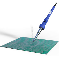
Attention, the product is a KIT and therefore you will be given the components to be soldered with an electronics soldering iron and everything needed to recreate the device as shown in the image. The KIT includes easy-to-understand illustrated instructions in English.
EXPERIENCE LEVEL REQUIRED medium-low
Assembly and testing by Mectronica STORE is also available by adding quantity 25 of the KIT assembly service .
INFORMATION | DOWNLOAD ARDUINO LIBRARY | PC SOFTWARE
Shield equipped with RS485 interface, micro SD card reader and 3-contact XLR connector. Combined with Arduino and free software with which we can build activation sequences (even synchronized to music), it allows you to control DMX512 interface devices from a PC. The micro SD card reader can be managed by Arduino in order to create multiple functions related to the control of DMX512 devices: for example, it can store activation sequences of lamps and devices for the show, to be reproduced following a command given by the computer or simply by the P1 button with which the shield is equipped. The shield is designed for a connection to a serial LCD display with which we can display information regarding, for example, the sequence being executed, the address assigned to the DMX512 device being controlled, the possible name of the sequence stored in the micro SD card, etc.
On request we can make applications using this board. For information you can contact us.
FIRMWARE
The firmware allows Arduino to create and send standard DMX512 command strings made up of a maximum of 512 bytes, each of which expresses 256 levels of brightness, or the movement of a rotor on which lighting fixtures or other devices are mounted, depending on the device being controlled. Each string begins with a header pulse followed in sequence by all the bits; each single-channel decoder/controller is set to interpret only its own byte, while decoders with multi-channel controllers interpret a range of bytes. For this to happen, each decoder counts the number of bytes starting from the header. It follows that to reach the decoder/controller marked by a certain address, Arduino must generate a string containing as many bytes as the channels up to that address: for example, wanting to control the peripheral that has address 128, our system must generate a string containing at least the first 128 bytes (those from 129 to 512 may not even be generated, because they are irrelevant, helping to maintain a good update speed of the DMX512 devices). The generation of the strings is provided by a library called DMXSimple (but there are others...) downloadable from the Google repository http://code.google.com/p/tinkerit/wiki/DmxSimple . Obviously you must include the library in your sketch. Two sketches are already provided in the library (you can access them with the Examples menu command): the first allows you to perform the fading (the fading...) of a DMX channel (see FadeUp, Listing 1) while the second allows you to set the value and the DMX channel via serial (see SerialToDmx). When setting the addresses of the peripherals to be controlled, remember what was said earlier, so if you have to intervene on a DMX512 decoder/controller, possibly set a low address for it; this will allow you to reduce the work of Arduino and speed up the scanning, so you can easily perform very rapid light games. In addition to the two example sketches contained in the library, you can download two more from our site called FadeUpHSV, which fades between the various RGB colors, and DMX_LightSequencing, which allows you to use the Vixen software, which runs on a PC in a Windows environment and allows you to build light control sequences by defining the channels to activate and possibly combining the switching on and off of lights or the activation of other DMX512 devices, at certain moments during the playback of a piece of music, which you can load from the same program. The two example sketches contained in the library and FadeUpHSV have been modified by us to be compatible with RGB lamps that can be controlled in DMX (for example the Velleman VDPLP-64SB lamp); therefore, in them it is sufficient to indicate the starting address of the DMX, then Arduino does the rest. Let's now focus on the fourth example sketch (Listing 2), called DMX_LightSequencing, because it is the one that allows us to interact with Arduino via a PC and therefore do the most interesting things; in this sketch, in addition to the starting DMX512 address, you also need to specify the number of channels to manage, meaning that you need to tell Arduino what the address of the first channel is and how many channels follow. In this way, Arduino will be able to build the necessary string, filling the positions corresponding to the addresses preceding the starting address with as many zero bytes as possible and ending the string with the byte of the address of the last channel. This, as mentioned, avoids wasting resources in reconstructing that part of the string that is not needed. The sketch must be used in combination with the Vixen program, which can be downloaded for free from http://www.vixenlights.com/ ; this software can run on practically any computer (the requirements are a 486 processor or higher, at least 128 MB of RAM and 2 GB free on the hard disk, Windows 98 operating system or later, as long as Microsoft .NET Framework is installed). With this software it is possible to create light sequences (but not only) possibly linked to music; one of the most suggestive applications is the combination with Christmas lights, of which you can see a small demo in this video, at https://www.youtube.com/results?search_query=vixenlights&oq=vixenlights . Vixen has different output formats including the serial one (unfortunately it is only possible to select COM 1, 2, 3 or 4) that we can use for a USB connection from virtual COM; by selecting the COM port to which Arduino is connected (Figure below "Sequence Plugin Mapping"), the software sends the value that each channel must assume. Arduino interprets this data and manages its digital I/O accordingly. Normally, in fact, the projects available in "network" provide that Arduino controls the lamps, or their controllers, through its digital outputs, but this greatly limits the number of usable channels (even using an Arduino MEGA the available ports are 54).
In our application, instead, we use the DMX library, which through the DMX shield allows you to manage 512 channels (including analog ones). In this way, it is possible to manage various peripherals other than classic lights, such as smoke and snow machines, strobes, rotating heads, etc. On the web you can find many ready-made sequences; the only thing to do is to set the output of the sequence (i.e. the serial port) and program Arduino by indicating the number of channels used in the sequence.
At the web address http://www.landolights.com/main/component/option,com_remository/Itemid,54/func,select/id,3/ you can find some sharing sequences, which can be used to control lamps, projectors and light strips with DMX interface, which will color any event with light.

You might also like
Shield equipped with RS485 interface, micro SD card reader and 3-contact XLR connector.